


The Shedding Light on Electricity series exposes the shocking truth about electricity. Yes, positively a bad pun to begin with, but we promise to conduct ourselves really well from now on. This series teaches students watts of stuff (sorry, couldn’t resist) about electricity including how it’s produced, how it’s used in our homes, how it’s controlled, and how we keep ourselves safe from nasty shocks. Ohm my goodness, this series is without parallel!
In Episode 4, Voltage, Current, and Resistance, we look at how electrical equipment is designed to use the right amount of current for the voltage supply that it’s designed for. After a brief recap on electric current (that we examined in Episode 3) we look at what voltage is and how it is measured. We then look at the concept of resistance. At a simple level, some materials are conductors and some materials are insulators, but not all conductors conduct equally well. The amount of current that flows in a household appliance depends on the appliance’s resistance!
A 5-minute excerpt followed by a 1 minute trailer.
 The Episode 4 Question Sheet for Students:
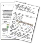
![]() The PDF version.
The PDF version. ![]()
Google The Google Doc version. Google
Get the answers.
![]() If you have ClickView, watch the whole episode here.
If you have ClickView, watch the whole episode here.
![]() If you have Learn360, watch the whole episode here.
If you have Learn360, watch the whole episode here.
![]() If you have Films on Demand, watch the whole episode here.
If you have Films on Demand, watch the whole episode here.
![]() If you have Classroom Video, watch the whole episode here.
If you have Classroom Video, watch the whole episode here.
![]() Most of our videos are also available on SAFARI Montage. Just log in and do a quick search.
Most of our videos are also available on SAFARI Montage. Just log in and do a quick search.
 Check out the outstanding practical activities that accompany this series!
The Transcript (which can be used as a textbook)
Contents:
Part A: Introduction
Part B: Conductors and Insulators
Part C: Voltage and Current
Part D: Resistance

Part A: Introduction
Hi everyone. In this episode of the Shedding Light on Electricity unit, Episode 4, we’re going to look at the three most important concepts in electricity: Voltage; Current; and Resistance, and at how they’re all related.
 Basically, voltage is a little like water pressure, current is, well like water current, and resistance is how difficult it is for the water to flow through the hose.
We already looked at electric current in a fair bit of detail in our last episode and we saw that different devices draw different amounts of current, even when they’re connected to the same power supply. In Australia, electricity is delivered at a voltage of about 240 V. All these devices are designed to operate at a voltage of 240 Volts, which is the supply voltage to all homes and schools and stuff in Australia and in fact most of the world.
This 2000 Watt heater for example draws about 8 Amps, but this 4 Watt light globe draws only about 0.02 amps even though they’re both connected to the same power source. (In Australia, all household sockets and light fittings are at a voltage of about 220 – 240 V.)
 These two light globes, which have different specifications, are connected to the same 6V power supply, but the current in the brighter globe is 0.27 amps while the current in the dimmer globe is only 0.06 amps.
How is it possible to control the amount of current in a circuit and design things like light globes that have different brightnesses? Well, using the concepts of voltage, current and resistance, that’s what we’re going to look at in this program. Let’s begin.
 Part B: Conductors and Insulators
At a simple level, anything that allows electric current to flow through it is called a conductor of electricity and anything that doesn’t is called an insulator.
Here I’ve set up a simple circuit with a power pack, a light globe, an ammeter, and a gap between which I can place different materials. The circuit will only be complete if whatever I place into the gap is a conductor. Aluminium, copper, nickel, iron (the bolt is actually made of steel but steel is about 99% iron), and zinc are all conductors.
 All metals are conductors of electricity, good conductors of electricity in fact. Another way of saying this is that metals conduct electricity.
The wires in houses and buildings are usually made of copper, while transmission-line wires are made of aluminium. Aluminium is a very light metal compared to other metals and it’s cheaper than copper, so that makes it both cheaper and easier to build the really long transmission lines and the towers that hold them. Copper is a slightly better conductor than aluminium which means that slightly less waste heat is generated when electricity passes through it, and that’s why it’s used for household wiring.

 However, insulators don’t conduct electricity. So, glass, rubber, cotton, paper, plastic, and ceramic materials, for example, are insulators; they don’t conduct electricity.
So, wires and light globes and the elements in heaters are conductors while the plastics used in switches for example are insulators. The electricity can travels safely through the wires but can’t get to you when you touch the switch.

 Now as we’ve seen, the filaments of these types of light globes allow electricity to pass through them, quite obviously. But, these two light globes have a different power output. Though they’re both connected to the same power source, the current in the brighter light globe is greater than the current in the dimmer light globe. This means that the filament in the brighter light globe, which is allowing more current to flow, must be a better conductor. The dimmer light globe resists the flow of current more than the brighter light globe does. We can say that this light globe has a greater resistance than the other light globe. Knowing the “resistance” of a conductor allows you to work out how much electric current will flow through it for any given voltage.
Also, knowing how much current you need allows you to design an electrical device that has the correct resistance.
Resistance, like current and voltage, is a measurable quantity and all three of these quantities, voltage, current and resistance are related to each other by a very simple formula: V = IR.
 Part C: Voltage and Current
So let’s look at voltage and current first.
We’ve seen that electric current, given the symbol I, is a measure of how many electrons are flowing past a given point in a circuit per second. A current of 1 amp means that 6.25 billion billion electrons are flowing through any given point in a circuit per second. There are that many electrons coming out of the battery per second, there are that many electrons entering and leaving the light globe per second and there are that many electrons going back into the battery per second. A current of 2 amps means that double that number, 12.5 billion billion electrons, are flowing through any given point in the circuit per second.
 Voltage is a measure of how much energy the electrons have as they move around the circuit. Voltage is a little like pressure. The more water pressure in this case, the more water current flows. If I connect this car reverse light to a 6 V battery, we get a current of 0.25 amps, but if I connect it to a car battery that supplies about 12.75 V volts, the current is 0.35 amps.
 The symbol for voltage is V, capital V, and its unit is the volt, which also has the symbol capital V. It’s actually very unusual for a unit and a quantity to share the same symbol. Voltage and its unit the volt were named after Italian scientist Alessandro Volta, who, in 1799 and 1800, invented the first battery that could supply a steady electric current. It was made of alternating copper and zinc discs with cardboard soaked in salt water between each disc. Thanks to this invention and to the discoveries relating to electricity that followed, the past 200 years or so of human history have seen more change than any other 200-year period by far.
 Connecting say 2 1.5 V batteries in series produces a voltage of 3 V, while connecting 6 1.5 V batteries in series produces a voltage of 9 V. Each battery boosts the energy of the electrons in the circuit.
Voltage is not measured at a given point in a circuit but between two points.
 In any operating circuit, electrical energy is provided by the power source and it’s converted into light energy or kinetic energy for example by the loads in the circuit.
If we go back to our water pump model, the voltage across the two terminals of a battery (which is about 6 volts for this battery) is a measure of how much electrical energy is given to the electrons by the battery, kind of like how much energy is given to the water by the pump between Point A and Point B. Voltage is a measure of the energy each electron gains. Voltage is also a measure of how much electrical energy is transformed (into kinetic energy or light energy or whatever) as the electrons move through the circuit component from one of its connections to the other or in other words it’s a measure of how much energy the electrons lose, kind of like the water’s energy being used up as the water falls from Point C to Point D which results in the wheel turning.
So, voltage is always measured from one point in a circuit to another and is a measure of the energy gained or lost by the electrons as they move from that point to the other. Voltage is of course mostly measured across one terminal of an electrical device to the other terminal.


 To measure voltage, I need a voltmeter which I have to connect in parallel with whatever I’m measuring the voltage of, because I’m measuring the energy difference of the electrons between two points in a circuit. Voltmeters used for experiments are similar to the ammeters that we saw in our previous episode. Here I’ve connected one of the wires to the black negative terminal, which is always used, and I’ve connected the other wire to the red positive terminal labelled 30, so I have to read off the 30 V scale, which is at the top.
So, in close up we can see that the 30 V scale is being used, so we ignore the other scales and read off the 30 V scale. Zero, 10, 20, 30. The needle is showing 6 volts.

 This device, which we saw in our last episode measuring electric current, can also measure voltage. The voltage of what is called “mains” electricity that our houses and schools are supplied with in Australia is about 240 Volts.
Multimeters can also measure voltage. I’ve turned the knob to the V (for voltage!) settings and specifically to the 20 Volt setting, which tells me that the multimeter will display up to a maximum of 20 Volts. I’ve connected one wire to the COM terminal and the other wire to the terminal labelled V?mA. This terminal is used when you’re trying to measure voltage, or resistance (that symbol is the omega, which we’ll talk more about soon), or current in milliamps. The reading for this AAA battery is 1.55 Volts.
 If I connect a light globe to this battery and then connect two multimeters (in voltmeter mode) in parallel with the battery and with the light globe (remember voltmeters are always connected in parallel with whatever you want to measure the voltage across), we can see that the voltage across both the battery and the light globe are the same: 5.98 volts. In a simple circuit like this, the voltage of the power supply is equal to the voltage across the two terminals of the light globe. This is probably not surprising.
 If I connect two light globes in series with each other, and then three multimeters in voltmeter mode in parallel across all three things, we can see that the voltage measurements across the two light globes add up to the voltage output of the battery. 5.90 = 3.09 + 2.81. The light globes are dimmer in series, since they’re only getting about 3 volts each. This is a major law of electricity: the sum of the voltages across each circuit component when connected in series is equal to the voltage of the power source.
 Now when components are connected in parallel, it’s a completely different story. Here I’ve connected a bright light globe and a dim light globe in parallel with each other to a battery. When I attach the voltmeters and measure the voltage across every component, we can see that they are all the same: 5.82 V. Any circuit components connected in parallel with each other will always have the same voltage across them. It doesn’t matter what the components are or how much power they use. The voltage across them is the same.
 This is a major reason that household lights (and appliances) are all connected in parallel. The fact that they can be switched on and off independently of one another is important (we saw that in Episode 2 of our series), and the fact that they will keep working even if one of the globes in the circuit blows is also important. But, just as importantly, all lights (and everything else)—connected in parallel—get the same voltage which is as I said 240 V in Australia, so you know how much power it’s going to use and how bright it will be regardless of what else is in the circuit.
 So the voltage across a component on its own is the same as the voltage of the power source, the voltage across components connected in series add up to the voltage of the power source, and the voltage across components connected in parallel are all the same, and they’re equal to the voltage of the power source. I should point out that the voltage supply of a battery actually varies a little in different circumstances depending on how fresh it is and on how much current it’s producing. It has to do with the chemical reactions that are going on inside the battery and how quickly they occur. However the circuit rules still apply!
By adding more light globes and components, more and more current is drawn but the voltage stays the same.
 Now in this circuit, I’ve connected an ammeter in series with a light globe to a fairly high-tech power pack that allows me to vary the voltage across its terminals. This arrow across the battery symbol is the circuit symbol for a power supply that you can vary the voltage of. If I now place a voltmeter in parallel with the light globe, we can see that as I increase the voltage across the light globe, the current in the light globe also increases. When I decrease the voltage, the current decreases. This relationship was first discovered and revealed to the world by German scientist George Simon Ohm in the 1820s.

 However, these light globes have different brightnesses even when they’re connected to the same 6 V battery, the lights in a car have different brightnesses even though they’re all connected to the same car battery, and light globes in our houses can have different brightnesses even though they’re connected to the same 240 Volt mains supply.
How do manufacturers make lights and other things that have different power outputs even when they’re connected to the same voltage source? Well, that brings us to number 3 on our list: resistance.
 Part D: Resistance
If I connect these two incandescent light globes to the same 6V battery, then they’re both getting 6 volts. The brighter one though must be drawing more current than the dimmer one, which is barely visible. I can add a multimeter in ammeter mode and see that the brighter one is drawing a current of 0.32 amps while the dimmer one is drawing a current of only 0.07 amps. The dimmer one resists the flow of current more than the brighter one and we can say that it has a higher electrical resistance, or simply, that it has a higher resistance.
 The resistance of an electrical component is a measure of how difficult it is for electric current to flow through it for a given voltage applied across it. Something with a higher resistance will resist the current more than something with a lower resistance. For any given voltage, a higher resistance means less current will flow.
Mathematically, the resistance of a component, given the symbol R, = the voltage across a component divided by the current flowing through the component. In symbols, R = V/I.
So the resistance of the dimmer light globe, R, = V/I which = 6 V (the voltage of the battery) over 0.07 A which equals 86.
The resistance of the brighter light globe = V/I = 6V/0.32 amps (the current running through it) which equals only 19.
The dimmer light globe has a higher resistance which means that it resists the flow of electric current more than the brighter light globe does. But we need to talk units. Resistance is measured in ohms (named after Georg Ohm, whom I mentioned earlier) and the symbol for ohms is the Greek letter omega (?). They didn’t choose the letter O because that letter can look like a zero so they went with the Greek omega: ohm, omega; they kind of sound the same. So we should put the unit in our answers. The dimmer light globe had a resistance of 86 ohms (?), while the brighter light globe has a resistance of 19 ohms (?).
Same voltage, but the light globe with about ¼ of the resistance gets about 4 times the amount of current.
Now the formula R = V/I can also be written as V = IR (this is how it’s usually written) and also I = V/R
Of course I didn’t really need to film the light globes separately. Remember, two light globes (or anything) connected in parallel to a 6 V battery both get 6 V across them each, just as all the lights in your house which are all connected in parallel, get 240 V each.
 So why do the two light globes have a different resistance? Well, the resistance of a wire is affected by four main factors: length, thickness, temperature, and the nature of the material that it’s made of. A longer wire has a higher resistance than a shorter wire, because the flow of electrons is resisted if the electrons have to smash into more atoms as they move around the circuit. A thinner wire has a higher resistance than a thicker wire because the current can flow more easily in a thicker wire, just like water can flow more easily through a wider pipe than through a thinner pipe. A higher temperature results in a higher resistance because at higher temperatures the atoms vibrate more vigorously so electrons have a harder time going through. The nature of the material is important because electrons can flow through some materials more easily than they can through other materials.
Light globes and all electrical devices are designed with different resistances depending on the voltage that they’ll be connected to and on how much current they need to operate correctly.
 So let’s examine the differences between this car headlight that is designed for a 12 V car battery and a household light globe that is designed for a mains 240 V supply. Both of these light globes are similar in their power output but they have vastly different resistances because they’re designed for vastly different voltages.
So what is the resistance of these two globes?
 Well, to find out the resistance of the headlight, I can connect a multimeter in ammeter mode in series with it to measure the current flowing in it when it’s connected and a multimeter in voltmeter mode in parallel with it to measure the voltage across it when it’s connected. If I now actually connect it, we can see that the voltage across it is about 12.3 V and the current in it is about 4.16 A. The resistance, R is therefore, V/I which is about 3 ohms.
This is actually a better way to measure the resistance of something than what I did before when I just assumed that the voltage of the 6V battery was exactly 6 V, but I thought I’d start simple for you and gradually get harder. By connecting an ammeter and a voltmeter in this way, you can get accurate measurements.
Now I can measure the voltage across and the current passing through this household light using this device.
 The light globe draws a current of 0.25 Amps and the voltage across it is 240 V although I’m not showing that here. Remember, the supply voltage for all lights and power outlets in Australia is 240 V. Its resistance is therefore R = V/I which equals 960 ohms.
Household lights that are connected to 240 V usually have much higher resistances than car lights because, since the voltage they’re connected to is much higher, they don’t need to draw as much current to get the same power output. The amount of power you get is related to voltage and current. So why are the resistances so different?
Well, as we’ve seen, there are four factors that can affect a wire’s resistance.
 Let me put up the details of the two light globes that we’ve looked at and see how they’re made differently. It’s not these last two that manufacturers change because the filaments of both globes are made of a type of metal called tungsten steel and they both reach temperatures of about 3,400°C which is the temperature needed for the tungsten steel to give off bright white light. Tungsten steel is used because it can reach these temperatures without melting. Most metals have a much lower melting point. So to change the resistance of the filaments, manufacturers change the length and the thickness of the filaments.
If we look up close, we can see that the 12 V headlight has a shorter and thicker filament while the 240 V household light has a longer and thinner filament, because it needs to have a larger resistance. It’s not just a coil, it’s a coiled coil.
Obviously all electrical devices, not just these kinds of light globes, are designed with all of these four factors in mind to draw the right amount of current.
Toasters, for example, use a metal called nichrome for their filaments. Nichrome has a higher resistance than tungsten steel, so the filaments can be made thicker, which means that they’re stronger and that they don’t break as easily.
 Now the resistance of ammeters and voltmeters is a really important factor in the way that they operate. As we’ve seen, if I want to measure the current in this simple circuit, I have to place an ammeter in series with the light globe. However, by adding an additional component, I’ve changed the circuit and so the current might now be different to what it was.
Adding an ammeter to a circuit does in fact change the circuit but only by a tiny amount because ammeters have a very, very low resistance.
The resistance of an ammeter is only about 0.01 ohms. I can add a second ammeter in series and there’s no measurable difference to the current in the circuit. The same holds true for multimeters in ammeter mode.
 Voltmeters on the other hand are connected in parallel with whatever you’re measuring the voltage of. So, voltmeters have a huge resistance, in the order of a few million ohms. As a result, only a tiny tiny amount of current flows into them. So, they also don’t really change the way that the circuit operates when they’re connected as long as they’re connected in parallel. In this circuit there are 290 mA running through the ammeter. At this point the current splits, but only a small fraction of a milliamp goes into the voltmeter because it has such a high resistance. Pretty much all of the 290 mA going through the ammeter go through the light globe. If I connect and disconnect the voltmeter, we can see that there is no real change in the circuit.
 So, just repeating, ammeters are always connected in series with whatever you want to measure the current in and they have a very low resistance, so they don’t significantly affect the current in the circuit. Voltmeters are always connected in parallel across the two terminals of the electrical component that you want to measure the voltage across. They have a very high resistance so practically no current flows into them and they too don’t significantly affect the circuit.
So, different electrical devices are designed to be fit for purpose. They also need to be safe of course. Generally they are safe and wires are all well insulated, but sometimes things break. So in our next episode we’re going to look a little more deeply into household electricity and at electrical safety. See you then.
Credits:
Written and directed by Spiro Liacos and produced by Liacos Educational Media.
Pila di Volta 01.jpg (http://commons.wikimedia.org/wiki/File:Pila_di_Volta_01.jpg) at the Tempio Voltiano, Como, Italy by Luigi Chiesa is licensed under CC BY-SA 3.0.